Note
SPI
Topics: Embedded Systems
Overview
Serial Peripheral Interface (SPI) is a synchronous, master-slave, full-duplex, serial communication protocol used for fast communication between microcontrollers and peripherals.
Interface
SPI requires four signals:
- SCLK (Serial Clock): Clock signal generated by the master to synchronize data transmission
- MOSI / PICO (Master Out Slave In): Carries data from the master to the slave
- MISO / POCI (Master In Slave Out): Carries data from the slave to the master
- CS (Chip Select): Active-low pin used by the master to pick which specific slave to talk to
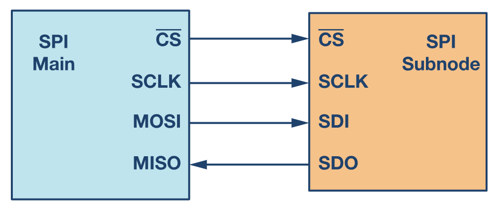
The main downsides of SPI compared to other protocols like I2C are that it only allows for one master and every peripheral device requires its own CS line. So, the number of pins and connections required grows with the number of peripheral devices.
SPI Modes
SPI clock behavior is defined by two parameters, Clock Polarity (CPOL) and Clock Phase (CPHA). As such, there are four distinct communication modes:
- Mode 0: CPOL = 0, CPHA = 0 (Clock idles low, data sampled on rising edge)
- Mode 1: CPOL = 0, CPHA = 1 (Clock idles low, data sampled on falling edge)
- Mode 2: CPOL = 1, CPHA = 0 (Clock idles high, data sampled on falling edge)
- Mode 3: CPOL = 1, CPHA = 1 (Clock idles high, data sampled on rising edge)
References
Backlinks
Notes that reference this page.
Connections
Direct relationships to this note.